Smartwatch: ATmega328P design vs RP2040 build
2026-08-04
I’ve built the same smartwatch twice: first as my A-Level Extended Project Qualification (EPQ) in 2018, then again as my Electronic and Electrical Engineering dissertation in 2022, this time with a machine learning twist. Repeating the same product gave me a clear measure of what four years of the degree changed.
Version 1, EPQ (2018)
EPQ Report (PDF) | EPQ Presentation (PDF)
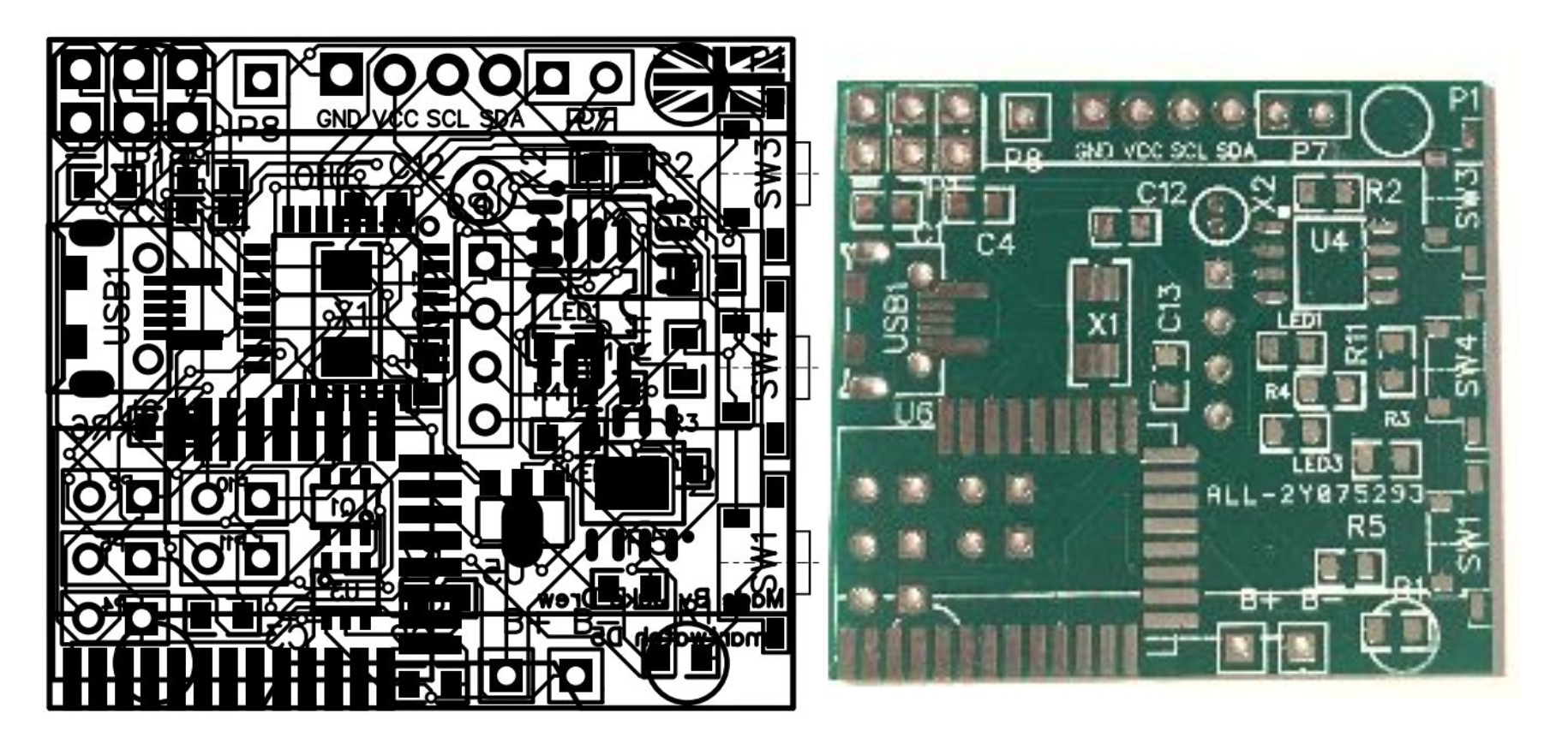
An ATmega328P design in EasyEDA with a 1.3-inch OLED, Bluetooth LE and LiPo charging, with every part chosen from its datasheet. It went through five revisions in three months and came to a £27 BOM. The eight boards were fabbed but never populated: I’d prototyped on a breadboard with an Arduino Uno, so every power figure was calculated, not measured. It was a design, not a device.
Version 2, Dissertation (2022)
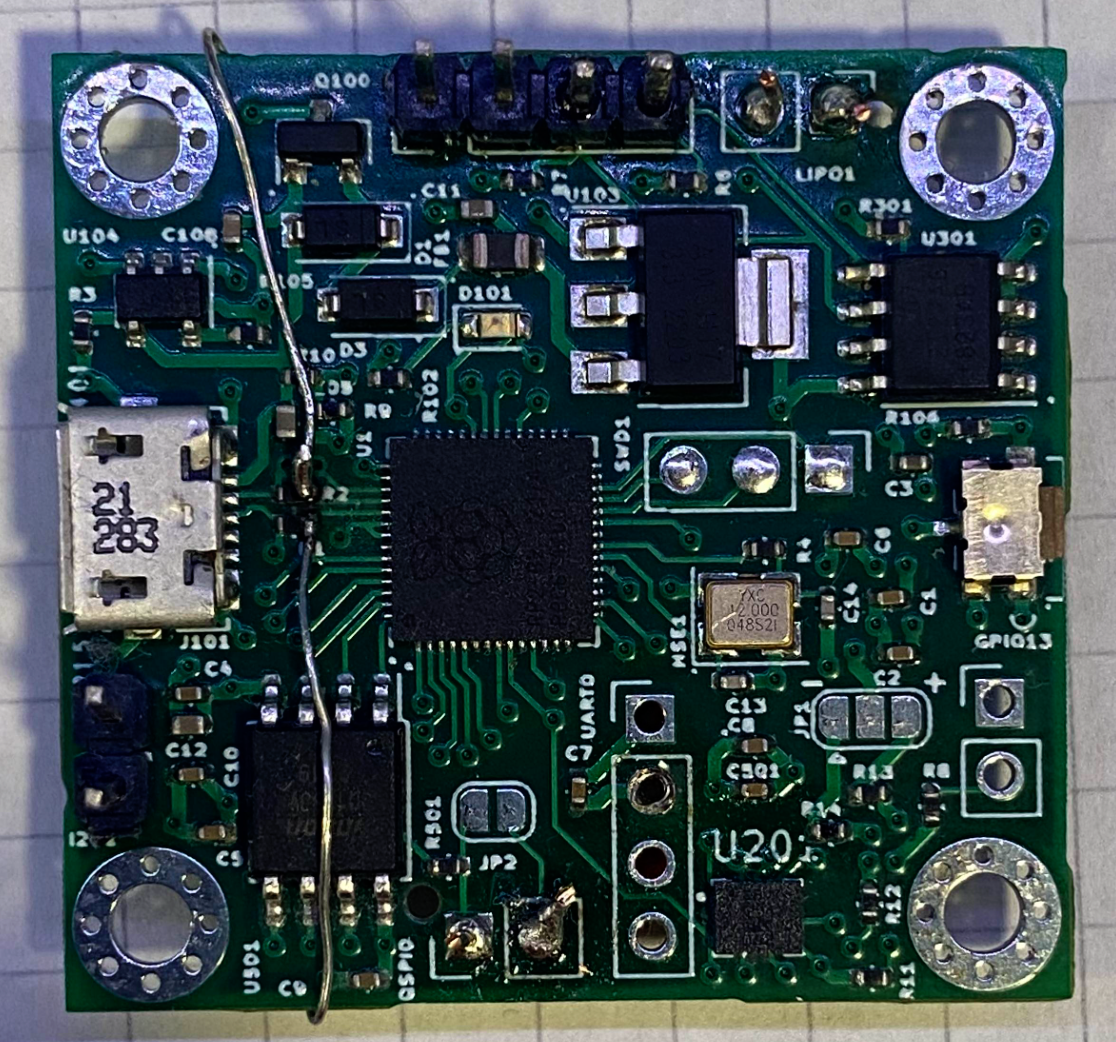
The dissertation rebuild was the same product done properly: an RP2040 (chosen at £0.52 against a £4.39 STM32), laid out in KiCad on four layers and assembled by JLCPCB, this time I went with everything machine placed on one side so JLC could assemble the majority of the board. This allowed me to use parts which would’ve been pretty hard to do reliably without the use of a reflow oven. I could also shrink the resistors to 0402s throughout. The chip shortage forced me to swap the IMU mid-project when Farnell’s MPU6050 lead time blew past my deadline, so an LSM6DS3 went in instead.
Firmware was embedded Rust on rp-hal, a year into that ecosystem existing, running a DeepConvLSTM classifier I’d validated at 83.2% on a 1.8M-row UCI dataset, and deployed with TensorFlow Lite Micro on the watch.
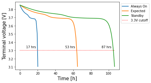
Battery life was simulated with PyBaMM from per-state current tables, 57 hours expected against a 2-day requirement:
The boards came back with 27.4kΩ for the USB termination but this needed 27.4Ω, my ordering mistake. This board revision was saved by the test pads I’d put on the underside “just in case” I needed to debug the USB which I could then connect some through-hole resistors to and then post fabrication fix this termination value. The one thing I still didn’t get done: no radio (WiFi/Bluetooth) made this board.
Changelog
2018-01-04 V1 Design complete, D5 schematic and Gerbers exported
2022-05-03 V2 Dissertation Submitted
2026-08-04 Note published